In the previous installment I provided a brief history of air quality in the cleanroom space. Essentially briefly chronicling the rapid rise of instrumentation followed by a need for standards to control the manufacturing of these instruments so they could better suit the industry they were serving. In this installment we’ll look a bit more closely at the ISO standard (specifically ISO 21501-4) that emerged. We’ll go through each of the requirements and discuss why this was included and what it sought to control. Ultimately, we’re attempting to lay the groundwork for a similar effort vis-a-vis air quality sensors in the air quality space. The hope is that understanding developments in industrial air quality monitoring will serve as a useful starting point.
ISO 21501-4 (or part 4) applies specifically to “Light scattering airborne particle counters for clean spaces”. There are certainly other ways to measure air quality, and in indoor and outdoor air quality most of the sensors are not particle counters, but it’s still instructive to use this standard point in discussing what an air quality instrument standard should address.
ISO 21501-4 has 11 basic requirements specified in and in order for an instrument to be compliant it must implement or pass all of these requirements. We’ll add each of these requirements in turn and attempt to explain the requirement, why it’s important and finally how it might apply to indoor or outdoor air quality measurement products.
In order to understand the standard it’s important to first define what a particle counter is. I think we’ve all had the experience of looking through a sunlit room and seeing particulates suspended in the air, caught in a sunbeam. A particle counter typically uses a very thin laser beam and passes the particulates through it essentially one at a time. As the particulates pass through the beam they scatter light with some of that light hitting a sensitive optical detector, the tiny signal from that detector is amplified into an electrical pulse, the height of that pulse corresponding very closely to the size of that particulate. The height of each of these pulses is measured and then particles are binned by size and counted. At the end of the sample the counts in each bin (or channel) are reported. In air quality applications, these counts are converted into an estimate of mass for each channel. In the figure to the right the air would enter the sensor through the inlet and exit through the outlet, as the air exits the inlet it passes through a laser beam (shown in red) and particulates would scatter light onto a detector (round object below it).
In air quality applications there are also sensors that measure aggregate mass instead of counting particulates. This is akin to taking a small portion of that sunlit room and looking at all the particles in that area and attempting to estimate the mass of the whole in one shot. They typically do this by measuring the scattered light of all the particles passing through the sensor over some period. They then assume that the particles that passed through the sensor over that period follow some regular size distribution (sometimes but not always the case) and then compare the result to a number of values recorded during calibration to arrive at an estimate of mass. The most expensive of these have some means of excluding certain particles by size (in subsequent samples) in order to refine their distribution estimate and improve mass estimates.
To calibrate a particle counter using ISO 21501-4 the manufacturer uses very special particulates with a tightly controlled size, shape and refractivity (typically polystyrene spheres from a NIST traceable source). I’ll omit discussing the calibration system in detail (since such discussion could easily result in several articles by itself), suffice it to say that these particles are aerosolized and presented to the instrument mixed with clean air such that these are the predominant particles passing through the instrument.
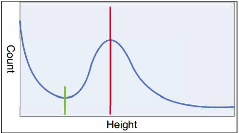
As these particles pass through the instrument they cross the light beam scatter light as described. Scattered light reaching the optical detector is amplified and the resulting pulse height recorded. In this case instead of binning it into a reasonably small number of channels (as we would when operating) a large number of bins are used to provide a lot of resolution to the sizing. We record a large number of particle heights during a sampling period and create a histogram of these (plotting the # of particles seen in each bin). This histogram looks something like the simplified plot in the image to the right with the blue line representing the histogram values with the counts in each bin on the Y axis and the height bins on the X axis. So, that as we move from right to left on the graph the particle pulses increase in height, from very tiny noise pulses on the far left to a few very large pulses (typically multiple particles passing through the beam together) on the far right.
The short green line indicates roughly where the noise threshold is. Generally height bins to the left of this line are considered to be “noise” (very small pulses and these will also typically be present in clean air). Height bins to the right of the green line are considered to be signal (these will only be present when the calibration particles are passing through the chamber). We can see that the bulk of the particle pulses are found between the yellow lines with the red line roughly indicating the median height of these calibrated particles.
Without getting bogged down in the actual detail we can then generally discuss the requirements for the standard in view of the above figure. In the text below I’ll use cleanroom applications to refer to the industry the standard was intended to address and then discuss thoughts as to how these might also be applied to more general air quality applications (which might include both indoor and outdoor air quality monitoring).
So with the above in mind here are the requirements for calibrating particle counters with ISO 21501-4.
1. Size calibration
This requirement states that the signal to noise ratio of a calibration channel be at least 2:1.
In the above figure that means that the number of counts for the height under the red line be twice the number of counts for the height under the green line. What we’re really attempting to do here is to ensure that we can discriminate particles from noise on the smallest channel and correctly identify particulates by size on the other channels.
For the cleanroom industry being able to size particulates accurately is a critical requirement since many manufacturing processes are highly dependent on the size of particulates in the environment and to the quantities of particulates at various sizes.
In air quality applications if we’re estimating mass based on particulate sizes and concentration then our estimate can only be as good as the accuracy of the sizing and counting in the instrument. Instruments that measure aggregate mass must rely on estimates of size distributions in the environment in order to attempt to attribute the total scattered light to estimate of particulate mass.
2. Verification of size setting
This requirement states that we be able to setup intermediate measurement sizes based on our calibrated sizes and that these new sizes be reasonably accurate(+/- 10% of the actual threshold).
If we calibrate our instruments for a handful of sizes, the user should be able to sort particulates by sizes we have not calibrated, with the instrument calculating the expected threshold of these sizes based on the sizes that were calibrated.
For cleanroom applications, the heart of a particle counter is its ability to discriminate particles by size. So, it’s critical that the sizing of all channels be reasonably accurate when calculating an intermediate size threshold.
In air quality applications, where we’re converting size channels and counts into mass having a large number of accurate channels is very important in arriving at a mass estimate. If the instruments are measuring aggregate mass then they are assuming a typical distribution of particulates by mass (which is often not the case).
3. Counting efficiency
This requirement states that our particle counts have to roughly match those on a NIST traceable instrument sampling calibrated particles in a common air stream. Omitting all the details of how this is done, we’re essentially ensuring that the counts we see on our instrument match those taken on a more sensitive NIST traceable instrument.
For cleanroom applications this ensures that two instruments report largely the same counts when sampling simultaneously from the same air stream. In order to pass this test an instrument has to accurately: control the air volume, process al/ the particles within that volume, size and count these particles, limit system noise, etc. So, this can be a very challenging spec to meet.
For air quality applications we need to arrive at a requirement that ensures that instruments from multiple vendors report similar results under the same conditions and that these do so without intermediation. At present many of these sensors compensate for poor quality sensing by doing significant manipulation of the sensor data in the cloud to turn sometimes nonsensical readings into something vaguely akin to an expected reality. This can grossly misrepresent the actual environment. There needs to be the means of validating that sensors report a reasonably accurate value without externally tampering with the data, to make them appear to be working.
4. Size resolution
This requirement states that the maximum width of the calibration histogram (area between the yellow lines) be 15% or less of the height bin for a “user” specified channel.
Essentially what we’re trying to control here is to keep the particle height bins reasonably tightly grouped so that we have significant separation between calibrated sizes and can tell the difference between particles of similar sizes.
For cleanroom applications this improves your ability to resolve intermediate sizes and size particulates more accurately, which is very important for many manufacturing processes.
For air quality applications sizing particulates accurately allows you to more accurately estimate mass.
5. False count rate
This requirement states that the manufacturer must measure the particle counts in clean air and that they should be statistically below some small threshold.
For clean room applications this is critical in that manufacturers often rely on an instrument to measure particulates in very clean environments so small numbers of “false” counts can be a big problem. There are always false counts, for example, cosmic rays are continually bombarding the earth and account for small numbers of counts. There are also other factors that can create such. The manufacturer must take measures to ensure that these are below a small statistically derived threshold.
For air quality applications the false count rate is much less important, in that the instruments typically operate in environments with large numbers of particulates. But if these false counts become a significant percentage of the actual counts then that error can impact the quality estimation. In sensors that measure aggregate mass this error manifests as a fixed baseline within the sensor (a minimum mass concentration) which gets added to any mass estimation error.
6. Maximum particle number concentration
This requirement states that the manufacturer must specify the maximum particle concentration that the instrument can operate in while still reporting counts within 10% of the actual counts.
For cleanroom applications this figure is typically of little use, since the environments are typically very clean, but it was added since some manufacturing environments where these instruments are used are much dirtier and these manufacturers wanted to ensure that the instruments can report accurately even during high particulate events.
For air quality applications this requirement can be crucial. There are many conditions where particle counts (and thereby mass) can soar, so having an instrument that can operate in high concentration environments is significantly more important. So, having some measure of the worst case environment in which an instrument can operate accurately should be specified.
7. Sampling flow rate
This requirement stipulates that the instrument must maintain the sampling flow within +l-5% of a target flow rate.
Typically if the instrument is unable to do so it would report a flow error. Early instruments often didn’t control or even measure the flow rate. In such cases, if the flow failed the instrument would blithely report erroneously low readings since less or no air was moving through the instrument.
For both cleanroom and air quality applications, ensuring that the flow rate is tightly controlled or monitored is critical in order to report reasonably accurate results.
8. Sampling time
This requirement states that the sampling period be accurately controlled.
In this day and age of microcontrollers with crystal controlled clocks this is a simple requirement to meet and is seldom an issue for instrumentation.
9. Response rate
This requirement states that when moving an instrument from a dirty environment to a clean environment that the instrument quickly respond and start reporting the clean air condition.
For cleanrooms this can be critical since some instruments are moved regularly between dirty and clean environments (when doing spot checking with a handheld instrument for example) and the user wouldn’t want to have to wait an extended period for the instrument to be useable in a clean environment after sampling in a dirtier environment.
For air quality applications this can also be important even for instruments that are mounted in fixed locations. You want an instrument to recover reasonably quickly from an event with elevated particulates and report correctly once that condition has been corrected.
10. Calibration interval
This requirement states that the manufacturer specify a suggested calibration interval for the instrument and perform at least size calibration, size resolution and counting efficiency and sampling flow rate calibration.
This article, by Particles Plus, Inc.’s Chief Technology Officer Davis Pariseau, originally appeared in the February 2019 issue of Healthy Indoors magazine.
 About the Author
David Pariseau is an embedded systems design en-gineer with 36 years of development experience in con-sumer electronics, financial payment, medical devices, lab instrumen tation, industrial controls, and machine design. David was the original founder of Lighthouse Associates (now known as Lighthouse Worldwide Solutions) in 1985, Technology Plus in 1995 and SinoEV Technologies in 2009. He co-founded Particles Plus in 2010 which is focused on bringing quality products into the mainstream commercial air quality monitoring space. He can be reached at dpariseau@particlesplus.com